

Multi-meridian corneal imaging of air-puff induced deformation for improved detection of biomechanical abnormalities
Biomedical Optics Express 2020 | Vol. 11 Issue 11, pp. 6337-6355
Andrea Curatolo, Judith S. Birkenfeld, Eduardo Martinez-Enriquez, James A. Germann, Geethika Muralidharan, Jesús Palací, Daniel Pascual, Ashkan Eliasy, Ahmed Abass, Jędrzej Solarski, Karol Karnowski, Maciej Wojtkowski, Ahmed Elsheikh, and Susana Marcos
Abstract:
Corneal biomechanics play a fundamental role in the genesis and progression of corneal pathologies, such as keratoconus; in corneal remodeling after corneal surgery; and in affecting the measurement accuracy of glaucoma biomarkers, such as the intraocular pressure (IOP). Air-puff induced corneal deformation imaging reveals information highlighting normal and pathological corneal response to a non-contact mechanical excitation. However, current commercial systems are limited to monitoring corneal deformation only on one corneal meridian. Here, we present a novel custom-developed swept-source optical coherence tomography (SSOCT) system, coupled with a collinear air-puff excitation, capable of acquiring dynamic corneal deformation on multiple meridians. Backed by numerical simulations of corneal deformations, we propose two different scan patterns, aided by low coil impedance galvanometric scan mirrors that permit an appropriate compromise between temporal and spatial sampling of the corneal deformation profiles. We customized the air-puff module to provide an unobstructed SSOCT field of view and different peak pressures, air-puff durations, and distances to the eye. We acquired multi-meridian corneal deformation profiles (a) in healthy human eyes in vivo, (b) in porcine eyes ex vivo under varying controlled IOP, and (c) in a keratoconus-mimicking porcine eye ex vivo. We detected deformation asymmetries, as predicted by numerical simulations, otherwise missed on a single meridian that will substantially aid in corneal biomechanics diagnostics and pathology screening.
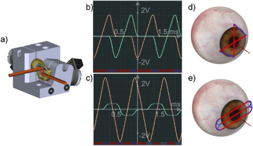
Figure: Galvanometric scanning mirror system and ultra-fast transverse scanning patterns. (a) Saturn 1B system 3D CAD model. Graph of input voltage (yellow and cyan) and encoder position voltage (magenta and green) sent to and received from the system digital signal processing board for the x and y galvanometer, respectively, vs. time for the (b) “cross-meridian” pattern; and the (c) “three horizontal planes” pattern. Corresponding scan traces, represented on a schematic eye, where the red lines indicate the phases during OCT signal acquisition, and the purple and blue lines indicate transition phases without OCT acquisition, for the (d) “cross-meridian” pattern; and the (e) “three horizontal planes” pattern.